If you’ve been in the field of engineering for even a short time, you’ve undoubtedly heard the term ‘fatigue’. But have you ever thought about what it actually is, why it matters and how we can go about predicting it? If not, this post is for you! And hey, it might be a good refresher for the experts out there too?
A (Very) Brief History Of Fatigue
Fatigue has been the scourge of engineers since we started making things! While we’ve always understood that every material essentially has a breaking point when it is overloaded, it wasn’t until the mid-1800s that engineers became aware of and documented the term ‘fatigue’.
Jean-Victor Poncelot was a designer of cast iron axles for mill wheels and it was he who officially coined the term ‘fatigue’ for the first time. In his book on mechanics, he proclaimed that the axles became ‘tired’ or ‘fatigued’ after being in use for a long time and then began to break apart.
Since then, fatigue has been studied by thousands of mechanics practitioners and is reasonably well understood in terms of mechanisms… Although it’s still not as easy to predict as we’d all like – see below!
Examples Of Fatigue Failures
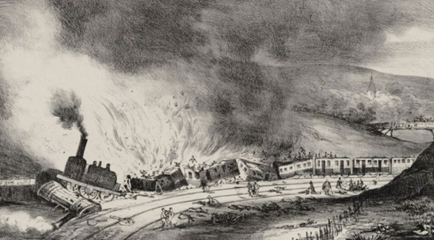
One of the most infamous examples of fatigue failure was the Versailles train crash of 1842, in which more than 50 people lost their lives. Of course, back then, the engineers were probably not even aware that the failure of the locomotive axle was fatigue related, but, looking back, we can be reasonably sure that it was.
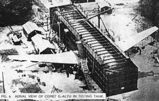
The De Havilland Comet plane crashes of 1954 were really a turning point in our understanding of fatigue. Many will have heard of the square windows and the fatigue cracks that developed from the stress concentrations there, leading to catastrophic failure of multiple aircraft and the subsequent grounding of the entire fleet. Full scale ground testing of the plane (shown below) led investigators to the conclusion that fatigue crack growth was the cause of these disasters, and this effort really paved the way for the understanding of fatigue behavior that we have today.
However, we’re still seeing catastrophic failures of mechanical equipment in the modern era that are attributed to fatigue. Just this year (2021), a 777 took off from Denver only to turn back shortly after takeoff due to an engine explosion and subsequent fire. On closer inspection of the damage, it became apparent that an innocuous fatigue crack in one of the plane’s titanium fan blades had extended far enough (over thousands of flight hours) to cause it to break off and destroy the engine and cowling.

Other notable examples of fatigue failure include:
- The Boston molasses disaster of 1919, in which a 2.3 million gallon tank of molasses broke due to fatigue at a manhole cover, releasing a 25 foot high wave that destroyed everything in its path.
- The Alexander L. Kielland oil platform capsized in 1980, killing more than 120 workers. This disaster was the result of a fatigue crack in the bracings of the rig. The crack was traced back to a 6mm fillet weld, which was structurally significant and poor in quality.
- The Eschede train disaster of 1998 in which a high-speed train in Germany derailed, killing over 100 people and injuring 100 more. This was caused by fatigue damage to a steel tire on one of the front carriages that eventually broke off and caused a chain reaction of car derailments.
Mechanisms
As mentioned earlier, the mechanism(s) of fatigue are reasonably well understood at this point, thanks to the efforts of many different researchers in the space. Essentially, fatigue can be broken down into three phases: initiation, propagation and ultimate failure.
Initiation
Perhaps the most difficult aspect of fatigue to predict is initiation. This is because the process is affected by so many outside variables such as material, stress level, mean stress, microstructure, surface roughness, material quality and many more. We’ll talk about the effect of these factors in future posts but, for now, let’s just stick to the basic principles.
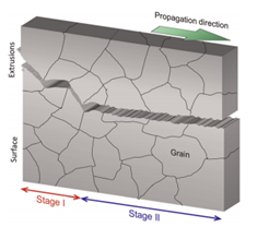
Essentially, fatigue occurs in regions of highly cyclic stress, which causes very local hardening of the material. Once the material has hardened, the stress amplitude in the (very local) area is increased and causes it to break down, forming what are known as persistent slip bands or PSBs. As shown in the figure below, once the PSBs begin to form extrusions and intrusions on the surface of the material, they themselves concentrate stress and act as tiny cracks or notches. Once these features become large enough to be classed as microcracks, fatigue failure is initiated.

Propagation And Failure
Propagation of a fatigue crack can, itself, be broken down into two stages. If the cyclic plastic zone, in which slip takes place, is smaller than the characteristic grain size, then we can consider the crack to be in stage 1 of its propagation phase. This is characterized by a jagged path that is highly affected by the dimensions and the orientation of the grains through which the crack grew. Once that plastic zone outgrows the characteristic grain size, the crack begins to grow in a direction more perpendicular to the stress (see figure).
Once the crack is of a sufficient size, reducing the cross-sectional area of the structure or test specimen, fracture mechanics takes over and the component fails (often) catastrophically.
Fatigue Prediction
Theory
25 years after the Versailles rail disaster, Wohler presented his work on metal fatigue curves at the Paris Exhibition. In fact, the research was a direct result of the disaster, and was really our first foray into the prediction of fatigue behavior.
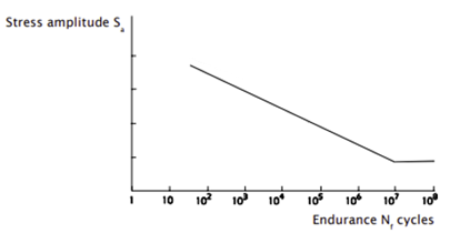
Of course, the curves he presented were SN curves similar to the one shown below. They are essentially a relationship between the cyclic stress or load level applied to a component and its respective number of cycles to failure. Typically, we’ll plot these on a log-log scale such that the line is straight and has a very clear end point, which we term the fatigue limit. This is the stress at which, no matter how many cycles we expose the material to, no damage occurs and life can be considered ‘infinite’.
If we were to expose our engineering components to multiple different types of cyclic load over their lifetime (which we almost always do in real life), it is important that we can still calculate life. Miner’s rule allows us to do just that. Essentially, the fraction of damage caused by each load type can be combined and allowed to accumulate until the total damage is equal to 1, at which point, fatigue failure (or at least initiation) will occur:

where nm is number of cycles at a given load level and Nm is allowable number of cycles.
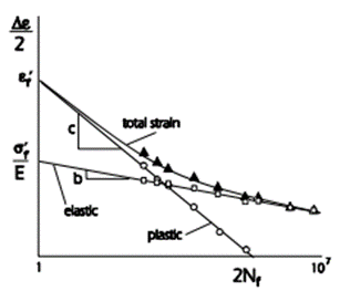
As well as SN curves, we can also look at fatigue in terms of strain – in EN curves. In this case, the elastic strain and the plastic strain components of each reversal (half cycle) are combined, as shown in the figure below, which is particularly useful where life is very low and we expect to have significant plasticity at the initiation site.
As mentioned earlier in this blog, there are dozens of factors that affect the initiation and growth of fatigue cracks – way too many to go into here. We plan on releasing blog posts periodically that discuss these effects and the methods that we can use to help account for them in our predictions, so keep an eye out for those!
FEA And Fatigue Codes
Again, without getting into too much detail regarding the complexities of most FEA and fatigue solvers, the workflow is essentially: 1) run an FEA model to predict stresses and strains for one (or one half of a) load cycle, 2) read relevant output data from each node (often just on the surface) into the fatigue solver, and 3) use the fatigue solver to calculate life based on the FEA results and some other inputs (things like algorithm selection, load scaling, surface finish, etc). Typically these codes are aimed at predicting initiation of fatigue cracks but, with the help of some fracture mechanics concepts, we can then switch back to our FEA solver to predict propagation and ultimate failure too.
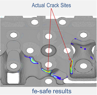
There are many different fatigue codes on the market but, of course, our particular favorite is fe-safe. This SIMULIA product can be accessed with extended tokens and works seamlessly with Abaqus, making them the perfect pairing for any durability-based engineering problem. Another significant benefit of fe-safe over its competition is its ability to consider both stress-based and strain-based fatigue problems, making it super robust – whether you’re in the low, high or very high cycle regime. On top of that, fe-safe has industry-leading capability in the fatigue prediction of welds and rubber materials.
Final Thoughts
Fatigue is a pain for designers. It is not something that we can easily design out of our parts like yielding or fracture – and it sneaks up on you after thousands or sometimes millions of innocuous loading cycles. It has been responsible for many of the most horrific engineering disasters and countless lives, yet we still struggle, as engineers, to nail it down.
Hopefully this post has laid down some of the basics regarding fatigue. We plan to fill in many of the gaps over the coming months, so keep an eye out for more posts like this!
If you’re interested in solving fatigue problems using simulation, ,don’t hesitate to get in touch. Our engineers have many years of experience in fatigue and fracture, and we’d love to talk to you!
