One of the most common questions you’ll hear asked in the FEA community is “What mesh size should I use?”, and for good reason! If your mesh is too coarse, the answers that you generate may not be as accurate as you need them to be. Conversely, if your mesh is too fine, the simulation will take much longer to run without providing any substantial improvement in accuracy. Unfortunately, there is no clear-cut formula for determining the best mesh size to use in every situation.
In this blog, though, we will explore a couple of different strategies that can be used to help determine an appropriate element size that will provide accurate results efficiently.
FEA Mesh Sensitivity Study
The most scientific approach for determining the mesh resolution needed to obtain accurate results is to perform a mesh sensitivity study. To do this, simply run your model with several different mesh sizes and plot the resulting stress or displacement values. Your mesh size is considered to have “converged” when there is little observed change in stress or displacement value with decreasing mesh size.
To demonstrate a mesh sensitivity analysis, we have simulated a cantilevered steel rod using four different hexahedral (C3D8I) meshes. The predicted values for stress and displacement are provided, along with the required computational time for each simulation.
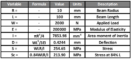
First, though, hand calculations can be performed to determine the expected values for stress and displacement. Calculation parameters and solutions are shown in the table below:
Analysis Results
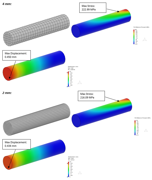
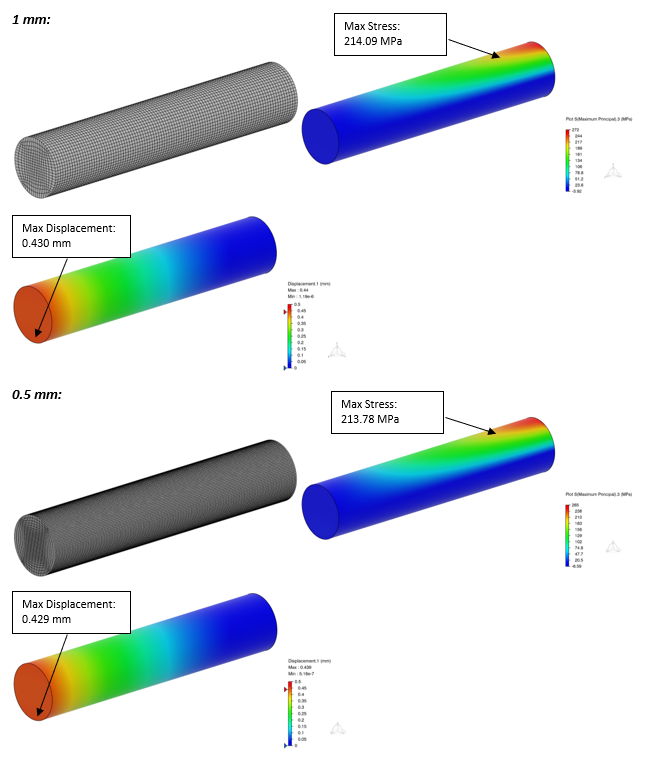

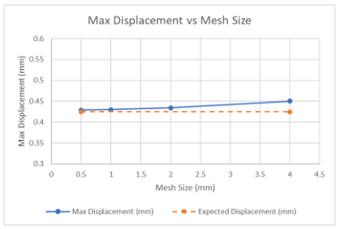
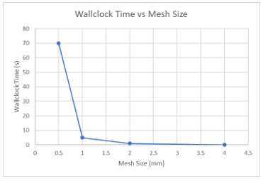
The expected displacement based on hand calculations is 0.4244 mm. As we can see from this study, as mesh size decreases, the maximum displacement converges toward the calculated value. However, it should be noted that the run time grows exponentially and provides diminishing marginal returns in terms of solution accuracy, as shown below.
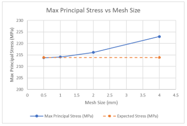
Because the maximum stress values displayed above were measured from a node slightly distant (0.16L) from the fixed end of the cantilevered beam, the calculated handbook stress used for comparison must be corrected, which results in a calculated stress value of 213.9 MPa (instead of 254.7 MPa). Stresses were measured at this location to avoid any artificial stress concentration effects imposed by the boundary condition at the fixed end of the beam. As mesh size decreases, the maximum principal stress values converge toward the calculated value. Also worth noting is that hexahedral elements are generally not the most appropriate elements to use in simulations involving bending since they are prone to shear locking. This effect can be somewhat mitigated through mesh refinement, but a better solution is to use C3D8I elements, which use an improved formulation intended to better capture such behavior.
Effect Of Element Type On Mesh Sensitivity
The type of elements used also affects the optimal mesh size. As shown in a previous blog about first- and second-order elements, a linear element like a C3D4 requires a small mesh size in order to produce accurate results, whereas a higher-order element like a C3D10 can still produce trusted results when using coarse mesh.
But how does that affect runtime? In the following example, the cantilevered rod is simulated again, instead using 1 mm C3D4 elements and 2 mm C3D10HS elements.
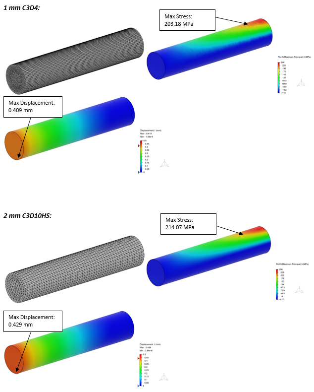
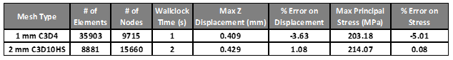
As we can see from this example, even though the C3D10HS element model has a larger mesh size, it still takes longer to solve since it has many more nodes. The stress values, however, are much more reliable when compared to the C3D4 elements (0.08% error vs. 5.01%).
Choosing Mesh Size Based On Geometry
Because we, as engineers, often have a good idea about how our parts will behave before we analyze them (or we should, at least!), one of the most effective strategies for choosing an efficient mesh size is to employ a hybrid approach based on the details of the part being analyzed (geometry, loading, boundary conditions, etc.). Areas where you don’t expect significant stresses can be coarsened to reduce the overall element count. This can help to provide an effective balance between simulation accuracy and the associated computation expense.
In the example below, a steel shaft with a flange is being analyzed in torsion. Because we’d expect the inner radius leading up to the flange to have the highest stress, we can locally refine our mesh and coarsen elsewhere.
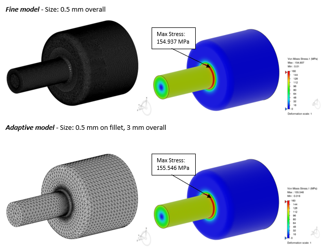
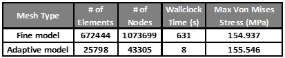
In the example above, the hybrid model solved nearly 80 times faster than the fine mesh model, yet stress results remained within half a percent of each other, which highlights the stark efficiency improvements that can be gained when employing this approach.
Final Thoughts
As you can see, selecting the right mesh size depends on your desired balance between accuracy and efficiency. Although second-order elements and refined mesh both improve simulation accuracy, they come with increased computational costs. Fortunately, simple mesh sensitivity studies can allow us to quickly understand these implications and employ hybrid meshing strategies that allows us to attain sufficiently-accurate solutions efficiently.
For more modeling, FEA, or CFD help, reach out to the team at Fidelis!
